Section 9.19 Shortest Path Problems
When you surf the web, send an email, or log in to a laboratory computer from another location on campus a lot of work is going on behind the scenes to get the information on your computer transferred to another computer. The in-depth study of how information flows from one computer to another over the Internet is the primary topic for a class in computer networking. However, we will talk about how the Internet works just enough to understand another very important graph algorithm.

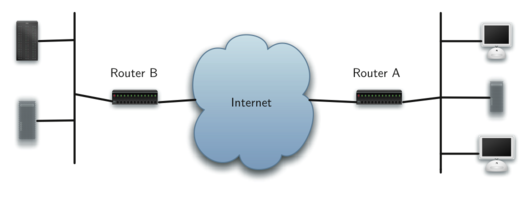
This image represents a simplified network diagram, showing an overview of connectivity in the internet. Two routers, labeled as Router A and Router B, serve as the central connection points. Router A is connected to a cloud labeled "Internet," which symbolizes the global network. On the right side of Router A, there are connections leading to a desktop computer and a laptop, representing end-user devices. On the left side of Router B, connected to the same internet cloud, are two server icons, indicating server machines. The diagram visually explains how different types of hardware devices interface with the internet through routers, depicting a basic structure of network connectivity.
Figure 9.19.1 shows you a high-level overview of how communication on the Internet works. When you use your browser to request a web page from a server, the request must travel over your local area network and out onto the Internet through a router. The request travels over the Internet and eventually arrives at a router for the local area network where the server is located. The web page you requested then travels back through the same routers to get to your browser. Inside the cloud labelled “Internet” in Figure 9.19.1 are additional routers. The job of all of these routers is to work together to get your information from place to place. You can see there are many routers for yourself if your computer supports the
traceroute command. The text below shows the output of the traceroute command which illustrates that there are 13 routers between the web server at Luther College and the mail server at the University of Minnesota.
1  192.203.196.1
2  hilda.luther.edu (216.159.75.1)
3  ICN-Luther-Ether.icn.state.ia.us (207.165.237.137)
4  ICN-ISP-1.icn.state.ia.us (209.56.255.1)
5  p3-0.hsa1.chi1.bbnplanet.net (4.24.202.13)
6  ae-1-54.bbr2.Chicago1.Level3.net (4.68.101.97)
7  so-3-0-0.mpls2.Minneapolis1.Level3.net (64.159.4.214)
8  ge-3-0.hsa2.Minneapolis1.Level3.net (4.68.112.18)
9  p1-0.minnesota.bbnplanet.net (4.24.226.74)
10  TelecomB-BR-01-V4002.ggnet.umn.edu (192.42.152.37)
11  TelecomB-BN-01-Vlan-3000.ggnet.umn.edu (128.101.58.1)
12  TelecomB-CN-01-Vlan-710.ggnet.umn.edu (128.101.80.158)
13  baldrick.cs.umn.edu (128.101.80.129)(N!)  88.631 ms (N!)


Routers from One Host to the Next over the Internet
Each router on the Internet is connected to one or more other routers. So if you run the
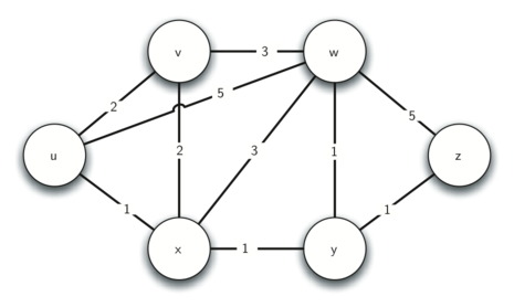
traceroute command at different times of the day, you are likely to see that your information flows through different routers at different times. This is because there is a cost associated with each connection between a pair of routers that depends on the volume of traffic, the time of day, and many other factors. By this time it will not surprise you to learn that we can represent the network of routers as a graph with weighted edges.

The image displays a weighted graph that models the connections and weights between routers in the Internet. The graph consists of six nodes, each representing a router labeled as u, v, w, x, y, and z. The nodes are interconnected by lines that signify the network links between routers. Each line is annotated with a number, representing the weight of the connection, which could indicate the cost, distance, or quality of the link. For instance, router u is connected to router x with a weight of 2, and router x is connected to router v with a weight of 2 and to router y with a weight of 1. This type of graph is typically used to represent the efficiency of data transfer paths in network routing algorithms.
Figure 9.19.2 shows a small example of a weighted graph that represents the interconnection of routers in the Internet. The problem that we want to solve is to find the path with the smallest total weight along which to route any given message. This problem should sound familiar because it is similar to the problem we solved using a breadth first search, except that here we are concerned with the total weight of the path rather than the number of hops in the path. It should be noted that if all the weights are equal, the problem is the same.
You have attempted of activities on this page.
