Every circuit in a computer is made by wiring together switches (transistors) so they implement logic gates. These logic gates are used to store information, do math, and make comparisons, as well as everything else a computer can do.
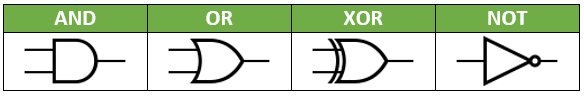
The diagrams for these circuits are drawn using the symbols shown below. Traditionally, the inputs to a gate come from the left, and the output comes out of the right side. That is why two lines are going into every gate but NOT… every other gate requires two inputs.
Below is an OR gate being used in a circuit. The power is wired to two push-button switches that function as the inputs to the circuit. The inputs can be turned off, in which case they do not transmit power, or on, in which case they allow power through (try clicking on the buttons inside Input1 and Input2 - the center will turn a different color when they are “on”). Those inputs feed into the left side of the OR gate. The output of the OR gate comes out of the right side and travels to the Output. If either one of the two Inputs is set to on (or both are), the Output should be on.