4.9. Abstraction Inside the CPU (optional)
Time Estimate: 45 minutes
4.9.1. Introduction and Goals
Abstraction In Hardware and Software
Abstraction is an important concept in CS -- and justifiably so. In fact, the history of computing can be seen as an advance from very primitive abstractions to very high-level abstractions.
Our App Inventor language is a great example of a very high-level abstraction. Consider the Camera component. App Inventor lets you take a photo by using a single Camera.TakePicture block in your app. But think about all of the very low-level operations that have to take place to focus the camera, gather and convert light rays into pixels and then into bits and then into an image file on your device. The App Inventor block hides all of that complexity.
- describe how abstractions in the CPU hide complexity and make a computer easier to use
- explain in detail how the CPU executes the instrucitons of a program
- use target vocabulary, such as machine language, fetch-execute cycle, and overflow error while describing abstractions within the CPU, with the support of concept definitions and vocabulary notes from this lesson
4.9.2. Learning Activities
Before There Was Software
To help us get a sense of this march through ever higher levels of abstraction, we're going to imagine ourselves back in the very first days of computing -- to the days before there was such a thing as software, when "programming" was a matter of manually inserting instructions and data into the computer, pressing the "run" switch and hoping for the best. There were no operating systems and blocks editors back then -- those abstractions came much later.
In the early days of computing, before there was software, virtually all programmers were women. Women 'computers', as they were called, wrote the first programs on the ENIAC, the first digital computer. But the story of the ENIAC programmers had not been told until just recently. Watch the trailer of a new movie. After watching, discuss with your classmates whether or not programmers used the same or different skills compared to what you're learning in this course.
Watch the ENIAC Trailer - Created with Studio G for Google I/O from Kathy Kleiman on Vimeo.

4-Bit Computer Simulator
The ENIAC weighed 30 tons. But in the hardware of the day it could store only 20 10-digit numbers in its
accumulators or memory registers. Programs had to be written by hand on paper and once the algorithm
was figured out, it would often take days to get the program into the ENIAC by manipulating its switches
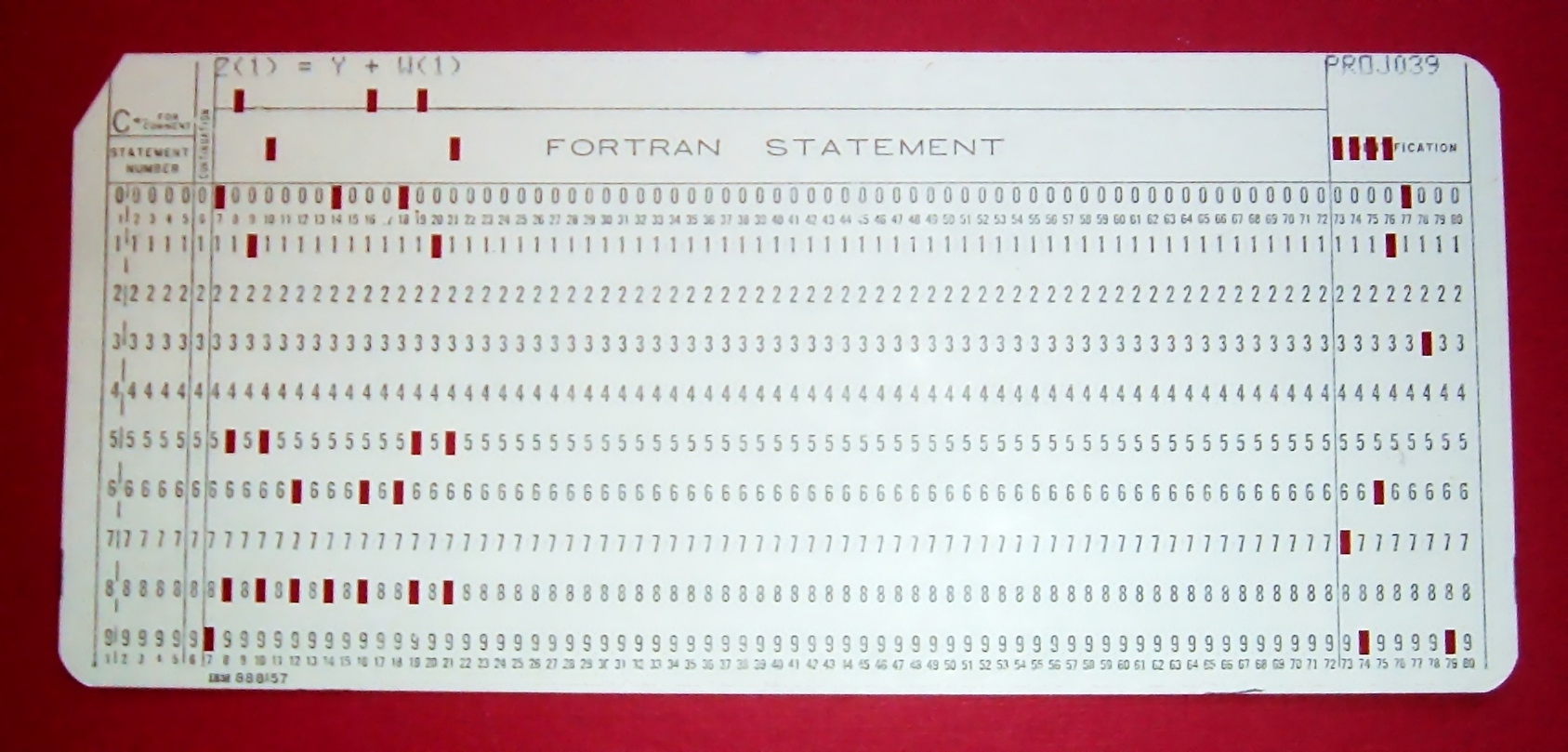
and cables. Later on, punched cards like the following were used to input programs or a simple addition calculation.

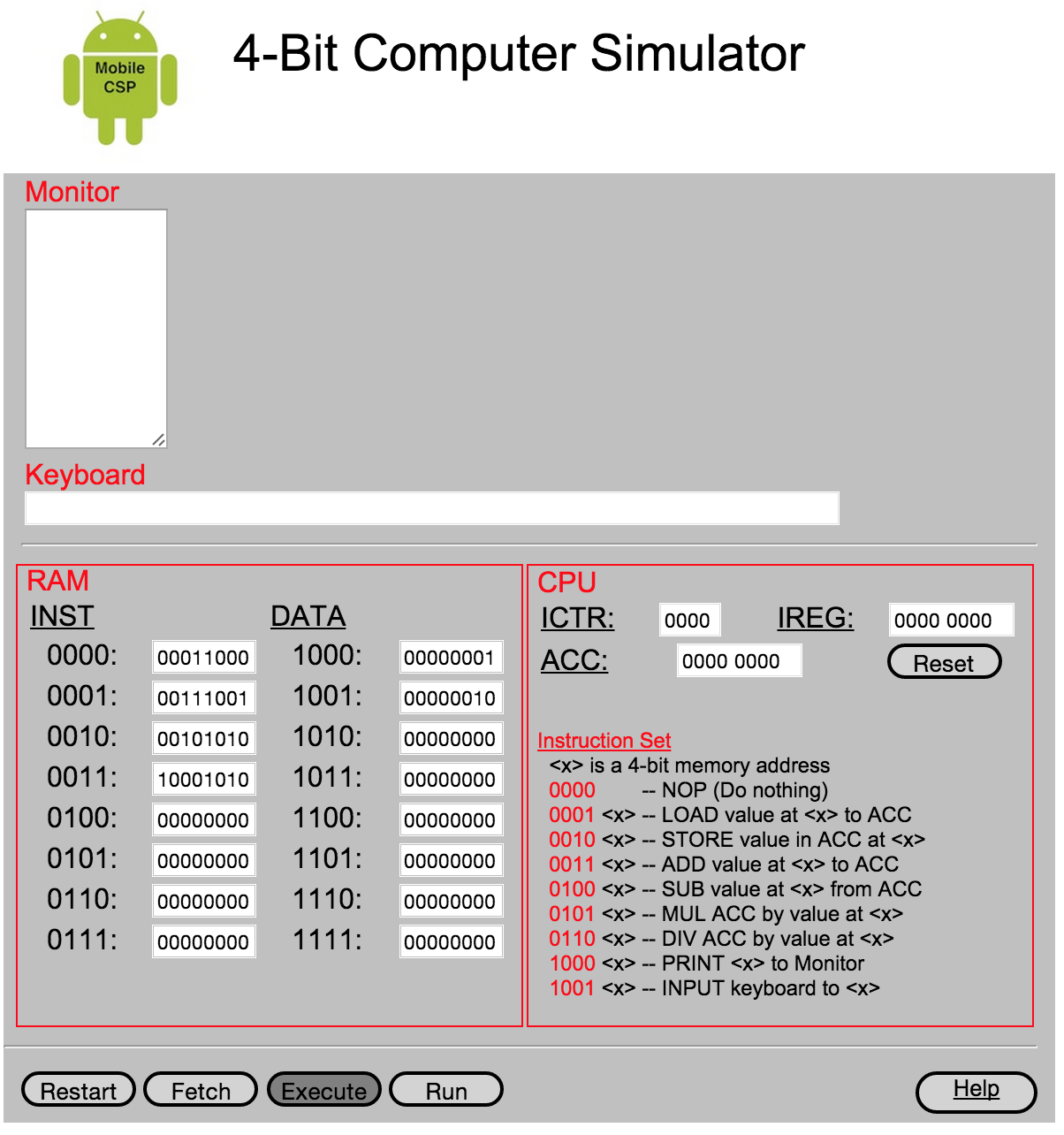
In this lesson, we will use a 4-bit Computer Simulator that has only 16 8-bit memory locations, so it's not that much 'smaller' than ENIAC. And like the ENIAC, it has little or no software. This will give you a hands-on sense of what programming was like before we had high-level languages and sophisticated programming platforms. It's also important to realize that the 4-bit Simulator is an accurate model of how today's computers work -- before your App Inventor programs can be run on your smart phones, they have to be translated into machine language, where they are interpreted by the CPU.
The videos and exercises below introduce the 4-bit computer simulator.
- Generation 0: Programming the raw machine. Just like the ENIAC women did, machine language programs have to be put directly into the computer's memory.
- Generation 1: Using an Editor and a Loader. Our first software abstractions will be an editor, which will let us type out the machine instructions, and a loader, which will load the instructions into memory for us.
- Generation 2. Using an Assembly Language. Instead of having to deal with 0s and 1s, our assembly language will give us a higher-level abstraction by letting us deal with symbolic names for instructions and data.
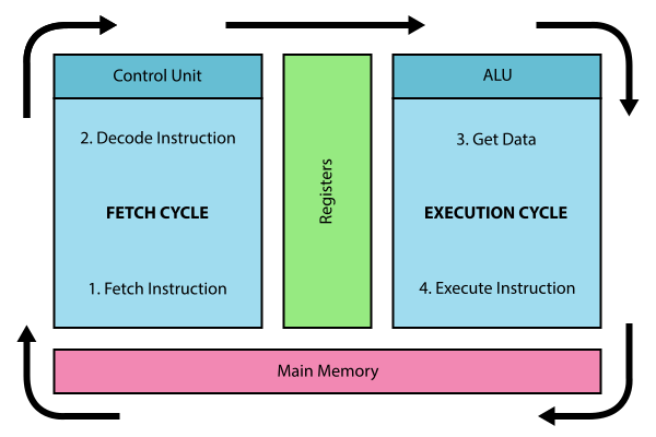
The simulator models a simple CPU Fetch/Execute Cycle like below but where the instructions are 1) Fetched from RAM, 2) Decoded in the CPU 3) Any needed data is fetched from RAM and 4) the operation is Executed in the CPU.

For each of the simulators below, watch the video and then in groups or pairs, do the self-check exercises after each video.
Generation 0: The Raw Machine
The video that follows takes us on a tour of the 4-bit computer. Perhaps the easiest way to follow along on the tour is to open the simulator itself in an adjacent tab and pause the video at spots to explore the simulator itself. Here's a link to the simulator that will open in a separate tab.
- The decimal value 3.
- Yes, when stored in a memory location, 0011 could represent the decimal value 3. So this is part of the correct answer.
- The machine instruction for ADDing a number to the accumulator
- Yes, if it occurred in the Instruction Register (IREG) or as part of a machine language program, 0011 would represent the machine language ADD instruction. So this is part of the correct answer.
- A memory location in the computer's RAM.
- Yes, memory locations in the 4-bit simulator have addresses that range from 0000 to 1111, so 0011 could be the address of a memory location. So this is part of the correct answer.
- The decimal value 17.
- If 0011 represents a number, then it would have to be a value between 0 and 15. The value 17 cannot be represented in 4 bits. So this is not part of the correct answer.
Q-2:
What is 0011?
In the 4-bit computer we can find several occurrences of the 4-bit string, 0011. What does this string of bits represent?
Choose all answers that apply.
Load the value at 1000 into the Accumulator
Add the value in 1001 to the Accumulator
Print the value in location 1010
Stop- This algorithm wouldn't work. The sum hasn't been put into location 1010 before printing it.
Load the value at 1000 into the Accumulator
Add the value in 1000 to the Accumulator
Store the Accumulator at location 1010
Print the value in location 1010
Stop- This algorithm wouldn't work. It would add 1 + 1 and print 2.
Load the value at 1000 into the Accumulator
Add the value in 1001 to the Accumulator
Store the Accumulator at location 1010
Print the value in location 1010
Stop- Yes, that is the correct algorithm. As you can see from the algorithm, in order to add two numbers, the numbers had to be moved into the Accumulator, a special register in the computer's Arithmetic Logic Unit (ALU) where all logic and arithmetic operations are performed. Even though the details are hidden from us now by the sophisticated software we use, today's computers still work the same way. When you add two numbers in App Inventor, software has to translate your program code into machine language instructions that load the numbers into the ALU registers before performing the addition and storing the numbers back to RAM.
Load the value at 1000 into the Accumulator
Add the value in 1001 to the Accumulator
Store the Accumulator at location 1010
Stop- This algorithm wouldn't work. It has no print statement.
Q-3:
What's the Algorithm?
Generation 0 of the 4-bit computer comes pre-loaded with a program that adds 1 and 2 and outputs their sum, 3. The value 1 in decimal is stored in location 1000. And the value 2 is stored in location 1001. Which of the following pseudocode algorithms correctly describes that program's machine language algorithm?
- Put the value 11111111 (decimal 255) in memory location 1000.
- Put the value 00000001 (decimal 1) in memory location 1001.
- Run the program and observe the output.
- 0
- Yes, the correct answer is 0. This would be an example of an overflow error. But it would not crash the machine. In binary, 11111111 + 1 = 100000000 (since 1 + 1 = 10 in binary which is 2 in base 10). This machine can only hold 8 bit numbers, but the answer 100000000 is 9 bits. This causes an overflow, where the left-most bit overflows the 8 bit memory space. Only the last 8 bits 00000000 are stored which gives the answer 0.
- 255
- No. You would get 255 if you added 0 to 255.
- 256
- No. The value 256 cannot be represented at all in 8 bits. In 8 bits you can represent 256 different values, ranging from 00000000 to 11111111, decimal 0 to decimal 255.
- No value. The machine would crash.
- No. Adding 1 to 255 in 8 bits causes an overflow error, but it would not crash the machine.
Q-4:
What's the Output?
Our 4-bit computer uses 8-bit bytes to represent its data. An 8-bit byte can store values ranging from 0 to 255 -- i.e., 00000000 to 11111111. What do you suppose would happen if you added 1 to 11111111?
To help answer this question, you might want to use the 4-bit simulator to write a little machine language program to see what happens. By default, the 4-bit computer adds the values in locations 1000 and 1001 and prints the sum. So here is how you would set up the machine to add 11111111 and 00000001:
What decimal value do you get when you add binary 1 to binary 11111111?
As you saw in the last self-check exercise, it is easy to see an overflow error when the 4-bit computer attempts to handle a number that is larger than the memory it has available. Even modern computers can occasionally have an overflow error when the computer attempts to handle a very large number that is outside of the defined range of values can be represented.
Generation 1: Machine Language Programming
Generation 1 of the 4-bit computer comes with some system software, software that today would be considered part of the computer's operating system. It provides an editor, which is software that lets you compose a machine language program, and a loader, software that will load the program into memory. This was similar to using punched cards to load in a program into a computer in the 1950s-1970s.
It also represents the first step toward a higher-level abstraction by freeing us from having to directly input values into the machine's memory. Instead, we can just type the program in the editor and the software will figure out how to load it into memory.
The following video will show you how this works.
Generation 2: Assembly Language Programming
Generation 2 of the 4-bit computer introduces some additional software in the form of an assembly language. Assembly languages were the first step in the direction of raising the level of abstraction used in writing and debugging programs. It's not a big step beyond machine language. But it does succeed in hiding some of the machine's underlying complexity, including the need to remember binary opcodes, memory addresses and data values.
The following video will show you how this works.4.9.3. Summary
In this lesson, you learned how to:
4.9.4. Still Curious?
Here are a couple of additional assembly language problems:
- Write an assembly language program that computes the square function for any valur x -- i.e., f(x) = x2. HINT: You'll need to use the INP operation to input the value for x. Once you have your program working, use it to help answer this question: Given that the 4-bit computer can only represent the numbers between 0 and 255, what's the largest value for x for which your program will work?
- Write an assembly language program that computes the value f(a,b) = a2 + b. HINT: Be economical. This program will barely fit into the 4-bit computer's memory.
The story of the ENIAC programmers is now told in a short documentary film that is freely available for viewing. If you want to watch it individually it is 20 minutes long (and may cost $5 to stream it).
4.9.5. Self-Check
Here is a table of the technical terms introduced in this lesson. Hover over the terms to review the definitions.
| RAM
CPU ALU machine language fetch-execute cycle |
instruction register
instruction counter accumulator assembly language overflow error |
4.9.6. Reflection: For Your Portfolio
Answer the following portfolio reflection questions as directed by your instructor. Questions are also available in this Google Doc where you may use File/Make a Copy to make your own editable copy.