- 0 cookies
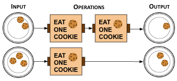
- There were only two "eat cookie" operations.
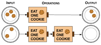
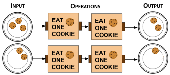
- 1 cookie
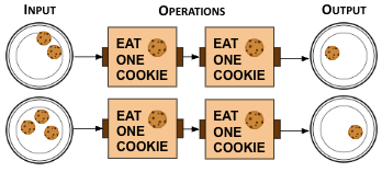
- Yes! Start with 3 cookies, eat 2 cookies, and you are left with 1 cookie.
- 2 cookies
- There were two "eat cookie" operations.
- 3 cookies
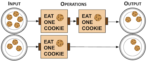
- You need to apply the "eat cookies" operations.
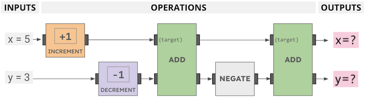
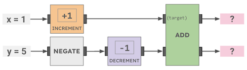
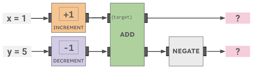
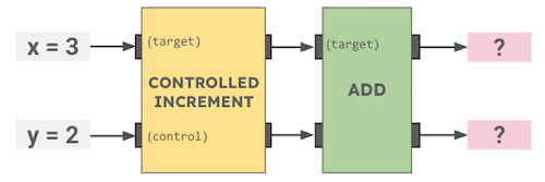
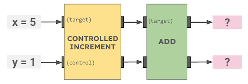
How many cookies will be left after this Cookie Circuit runs?
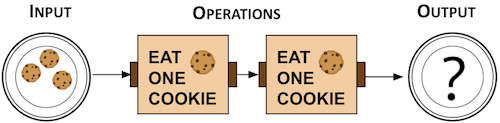
Hint.
Operations are read left to right